The World's Smallest Controllable Aircraft
January 17, 1999
The first design of the frame is shown in Figure 1. This design
shows the basic layout and design of the aircraft. Please note that
the details are confidential and therefore they have been
excluded from this picture and the ones following.
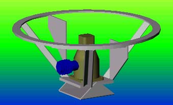
Figure 1: Initial Frame Design (Generated with AutoCAD R14).
January 19,1999
This next design has a few small changes over the initial design,
they can be seen quite easily in Figure 2.
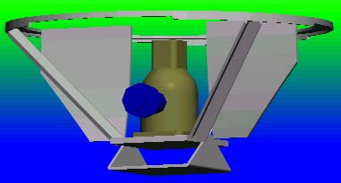
Figure 2: Next Stage Frame Design (Generated with AutoCAD R14).
Febuary 5, 1999
Currently I am choosing between using a Cox or a Novel engine. A test harness was built and used to test three different engines, two Cox engines and one Novel engine. The engines were tested for RPM, lifting weight, and fuel consumption. A motor has not yet been decided.
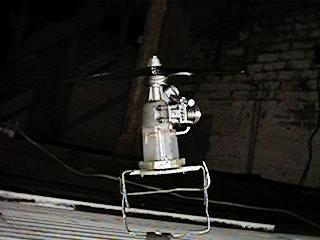
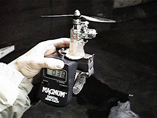
Figure 3: Initial testing/choosing of motor and
test assembly on the left.
March 10, 1999
The pieces to the actual craft were finally designed, cut and formed. The actual putting of the pieces together will not happen until a little later.
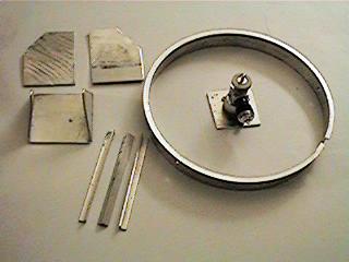
Figure 5: Pieces of the frame ready to be assembled.
March 18, 1999
Pieces of the shell were finally welded together thanks to the help of George Marostica and his excellent welding experience. Now the craft is almost ready for its first practise at free flight.
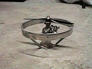
Figure 6: The engine and shell finally assembled.
April 15, 1999
There is a lot of balance required in getting an aircraft like this to fly. Below is the aircraft on one of the test stands built to test and correct one of these problems
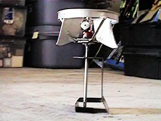
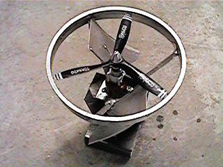
Figure 7: Chip on a balancing test stand.
October 10, 1999
Due to some stealing of ideas I've been reduced to showing only some details and no upclose shots or specific traits. Below in figure 8 is shown the completed shell of the aircraft, the electronics are not onboard.
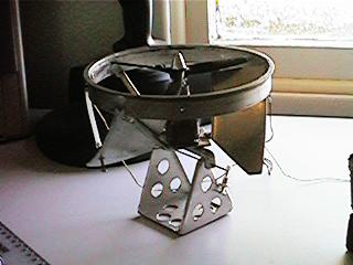
Figure 8: Chip mechanically complete, missing only the electronics.